End-Fed antennas do have their place in radio and
other communications work. Like everything else,
antennas come in many forms and flavors. It's up to
the designer to select the best design for the job at
hand and to utilize that design in the most efficient
way.
* * * A Bad Rap? * * *
- End-Fed antennas are NOT balanced systems; but
neither are verticals, ground planes, discones,
windoms, zepps, Marconis, half-slopers, et al.
Additionally, the low-impedance antenna port of your
transmitter/receiver is not balanced.
- End-Fed antennas are noise magnets. Really?
That's because most hams and SWL-ers don't bother
to interface them properly.
- End-Fed antennas have wild impedance swings. So
do all antennas, but not at the design frequency -
there, at the design frequency, the terminal
impedance is quite predictable.
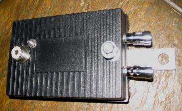
To make the best use of an End-Fed antenna, it
should be fed with a transformer. Here are some
photos of one of my 9:1 baluns. However, when
using it with an End-Fed antenna it is wired as a
(so-called) "unun" transformer (unbalanced to
unbalanced).
The raw End-Fed antenna will go through impedance
swings as high as 5K Ohms, or more, at even
multiples of its 1/4 wavelength design frequency. At
every odd multiple it will be at a more civil
impedance of between 36 and 90 Ohms. Using the
transformer, the magnitude of the impedance swings
is greatly reduced. This is due, in part, to the ratio
balancing of the transformer's turns (windings), and
to a few complex reactance and other physics
attributes that I won't try to cover here.
Additionally, the unun will eliminate (virtually) all
"common mode" currents on the feedline. This is
important for eliminating the pickup of local
electrical noise from homes and power distribution
lines. The coax, being connected to ground through
a DC path will eliminate all but the differential
currents ... pretty cool, huh?
Finally, since the antenna is connected directly to
Earth ground through the secondary of the
transformer, static buildup cannot occur - the
antenna is a dead (DC) short to ground. This is
important to sensitive, solid state radios.
The 9:1 transformer provides:
1. a much flatter broadband impedance
response,
2. a static elctricity-free antenna system
(no buildup),
3. common mode noise immunity (if
space wound as shown).
other communications work. Like everything else,
antennas come in many forms and flavors. It's up to
the designer to select the best design for the job at
hand and to utilize that design in the most efficient
way.
* * * A Bad Rap? * * *
- End-Fed antennas are NOT balanced systems; but
neither are verticals, ground planes, discones,
windoms, zepps, Marconis, half-slopers, et al.
Additionally, the low-impedance antenna port of your
transmitter/receiver is not balanced.
- End-Fed antennas are noise magnets. Really?
That's because most hams and SWL-ers don't bother
to interface them properly.
- End-Fed antennas have wild impedance swings. So
do all antennas, but not at the design frequency -
there, at the design frequency, the terminal
impedance is quite predictable.
To make the best use of an End-Fed antenna, it
should be fed with a transformer. Here are some
photos of one of my 9:1 baluns. However, when
using it with an End-Fed antenna it is wired as a
(so-called) "unun" transformer (unbalanced to
unbalanced).
The raw End-Fed antenna will go through impedance
swings as high as 5K Ohms, or more, at even
multiples of its 1/4 wavelength design frequency. At
every odd multiple it will be at a more civil
impedance of between 36 and 90 Ohms. Using the
transformer, the magnitude of the impedance swings
is greatly reduced. This is due, in part, to the ratio
balancing of the transformer's turns (windings), and
to a few complex reactance and other physics
attributes that I won't try to cover here.
Additionally, the unun will eliminate (virtually) all
"common mode" currents on the feedline. This is
important for eliminating the pickup of local
electrical noise from homes and power distribution
lines. The coax, being connected to ground through
a DC path will eliminate all but the differential
currents ... pretty cool, huh?
Finally, since the antenna is connected directly to
Earth ground through the secondary of the
transformer, static buildup cannot occur - the
antenna is a dead (DC) short to ground. This is
important to sensitive, solid state radios.
The 9:1 transformer provides:
1. a much flatter broadband impedance
response,
2. a static elctricity-free antenna system
(no buildup),
3. common mode noise immunity (if
space wound as shown).
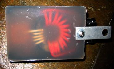
An Important Note on this Design
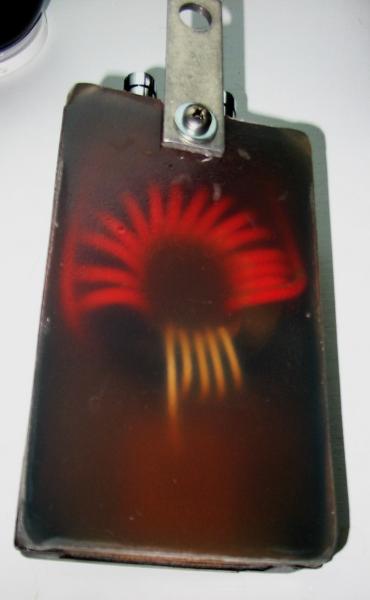
I selected the separate (spaced, opposite or complementary) winding format over bifiler or
twisted-pair winding in order to minimize the coupling effects of stray capacitance between the
primary and secondary windings. This symmetry is important to the quality of common mode noise
rejection, which is one of the balun's attributes - and should be exploited as such.
Construction of the 9:1 balun/unun: I used an old plastic box and a type 75 toroid core. My windings, in
this case, are for transmitting, using No. 10 and No. 14 solid copper wire. For SWL-ing a smaller core
can be used along with No. 18 or smaller wire. The turns ratio is 3:1 for a transformation of 9:1.
The impedance is the square of the turns ratio (Z=T^2). The antenna terminals are brass speaker
terminals and the low impedance side is a standard SO-239. The grounds of the two windings have
been isolated but, can be strapped together by the screw contacts (shown in the top photo). The
entire assembly was potted with marine fiberglass. Note that I also added a hanger strap for
convenience.
Testing the 9:1 balun/unun:
Properly designed and constructed toroid transformers are not lossey!!!
On the test bench with a 52 Ohm source and a 450 Ohm load the transformer shows a loss of no more
than 0.6 dB with about 0.45 dB being average, and the low reading of 0.2 dB.
Installation of the 9:1 balun/unun:
The End-Fed is connected to one terminal of the "high" winding and the other terminal is connected
to a good "EARTH" ground. One or more copper rods or pipes driven, at least, 4 feet into the earth
near the dwelling entry point (2 or 3, is better, being spaced about 4 feet apart). The coax is
connected to the SO-239 and fed to your radio. The best place for the balun for receive-only
antennas, is mounting it directly to the primary ground rod and keeping the ground conductors as
short as possible. Use a heavy copper wire (not steel or aluminum) or, better yet, low inductance
conductors which have an aspect ratio that is other than "round." The higher the aspect ratio, the
better, like flat copper braid or copper sheet metal strap. This, in effect, will give you an inverted "L"
antenna (of sorts), depending on the length of the vertical element. For transmitting, it's best to place
the transformer at the actual feed point, up, and away, from possible contact by humans and pets. Of
course, extra care must be taken to properly ground the balun by running the ground conductor down
the tree, house, etc. If your antenna is attached to your tower and ground-BONDED to the household
grounding system, as mine is, then you are home free ... just be sure your tower itself is properly
grounded ... you'd be crazy if it wasn't suitably grounded the day you put it up!!!
A word about grounds.
We are talking about RF (signal) ground on this page. These are the grounds that provide the antenna
counterpoise (true ground plane), and afford static bleed to NOT allow lightning's near field (DC
component) induction, or just general DC static electricity buildup on he wire, to pass along to your
radio. A balun will not stop the RF component of near-field strikes, although the inductive component of
the windings and ferrite will lessen its amplitude.
These grounds ARE NOT about electrical service safety. Smart people tie their radio grounds to a
common point "service ground" ("BONDING") with heavy gage wire, I do - and this is fine if ALL the
other ground measures discussed here have been met. Simply put: electrical service ground is NOT a
substitute for a good RF Earth ground, which is required for a good antenna system. In fact, your
service ground will probably be a very bad RF ground and a good source of (household /
neighborhood) noise, if not outright dangerous to you and your equipment. Remember, the "neutral"
wire in your circuit breaker box travels outside of your home and all around the neighborhood ... it's a
noise magnet and (going from pole-to-pole) a potential lightning rod!!! Best to consult with a licensed
electrician about "bonding" the entire household, IE: electrical service, cable service, telephone
lines, and RF grounds.
Technically speaking, that addition of outside antennas may modify or invalidate you home's fire
insurance coverage. If in doubt, contact your insurance agent. Also, consult with a licensed
electrician to be sure you conform to all NEC and local electrical codes for the proper BONDING of ALL
service grounds, and ground systems, within and about your home.
A 9:1 Balun
For Your End Fed Antenna
For Your End Fed Antenna
